Network Your Home Lab
BUILDING A HOME LAB OR SMALL OFFICE SOLUTION

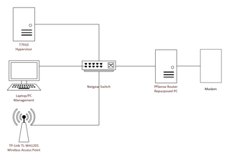
Networking your home lab or small office will be the most important part of this process to get right. Nothing will work as it should unless proper networking is configured. We need to establish our hardware we will use, software to manage our router, IP network range, scopes, subnets, and VLANs. It is much easier to manage if we document everything from the start rather than as we go. If you haven't completed the steps in Choose Your Hardware ensure you do and come back here when you are ready.
PREVIOUS: Choose Your Hypervisor
Configure Wireless Access Point, Router, and VLANs
In the case of home networks, your ISP may have provided you the popular ‘all-in-one’ Modem, Router, and Switch combo that acts as all three devices in one device. In small businesses, business enterprises, and home lab environments, will enjoy much better security and flexibility by having separate devices for each of these functions. We will cover converting your wireless router to a wireless access point only by placing it in Access Point (AP) Mode , using your old PC as our new PfSense Router with Firewall. PfSense wasn’t designed to be a Wifi access point nor a network switch so it will not perform those functions very well, hence why we are using dedicated hardware for those roles.
Option 1: Convert Home Router to a Wireless Access Point
Use this method if you don’t wish to purchase a separate wireless access point and wish to convert your existing router into a wireless access point (this also means you need to have an old PC available to use as your new PfSense router when we get to that step). Use Option 2 below if you have purchased the recommended wireless access point.
Instructions may vary by manufacturer, check your official router documentation for specific instructions.
Login to the router you wish to convert to a Wireless Access Point (WAP). If you don’t know the login information, you can always factory reset the device and use default credentials.
Set a static IP of 192.168.1.10
Place the router in ‘Operation Mode’ or ‘Access Point (AP) Mode’, if your router doesn’t have these options, manually disable services such as: DHCP, UPnP, NAT, any routing protocols. Reboot if prompted.
Use one of the LAN ports to plug into PfSense, ignore the WAN port on the router do not plug anything into it. Refer to the network diagram to ensure you are plugging everything into the correct ports.
This will now convert your router into a wireless access point that will bridge the wireless devices in your network into wired devices.
Option 2: Configure the TP-Link TL-WA1201 as your Wireless Access Point
Use this method if you wish to do away completely with your home router for this project. This may also be the preferred method if your current router is unable to be converted into a wireless access point.
Connect the TP-Link TL-WA1201 wireless access point to a laptop or PC and set a static IP within the subnet range of the WAP such as 192.168.1.0 or 192.168.1.1
Navigate to the default URL of “http://tplink.ap.net” and login using the default username/password of admin and admin.
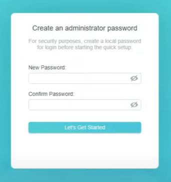
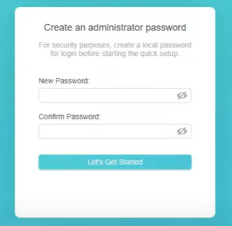
You are prompted to change the default password on the first screen upon login.
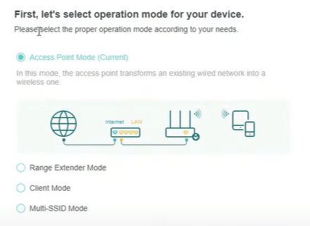
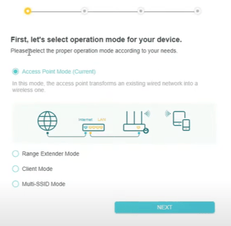
On the ‘Quick Setup’ page, select ‘Access Point’ as the operation mode and select Next,
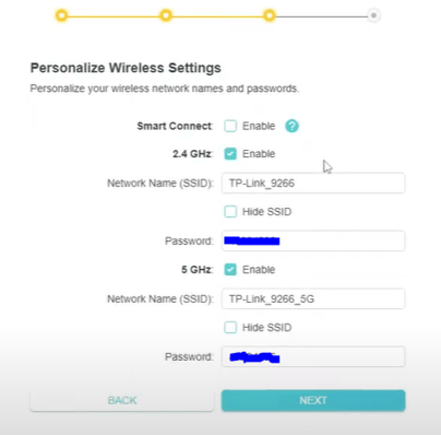
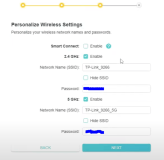
Set the correct SSID and password of your home/small office ISP and select Next,
Select the option to ‘Obtain an IP address automatically’ as we want the WAP to to send a broadcast request for a DHCP IP address,
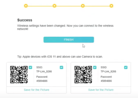
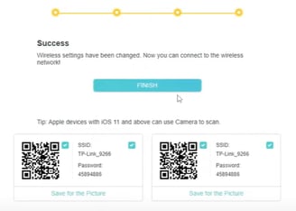
Select Next then Save.
Shutdown the WAP and connect to the Netgear managed switch on port 2.
Power on the WAP, it will be assigned a new DHCP address, you can locate the new IP address by logging into PfSense and navigating to Status->DHCP leases to see what IP was assigned. You shouldn’t need to administer this WAP any further, it will now start forwarding DHCP broadcast requests from your wireless devices such as iPhones, iPads, TVs, etc to your PfSense router. and you will receive a DHCP IP from the LAN interface. It has been my experience that things work better when you power off all wireless devices in your home network and turn them back on, most of the time they will receive a new DHCP address.
Turn an old PC into a Home Router and Firewall.
We will be using the free and open-source router/firewall called 'PfSense' and will be installing it on an old PC. Pfsense offers a Community Edition that we will use, it also offers features such as load balancing, unified threat management, and more. If you wish to install your PfSense router on a VM instead (as it wouldn't require buying or converting hardware), see the 'Double NAT using Bridge Mode' section below.
Download the latest PfSense image
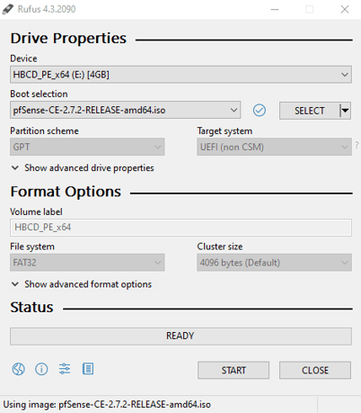
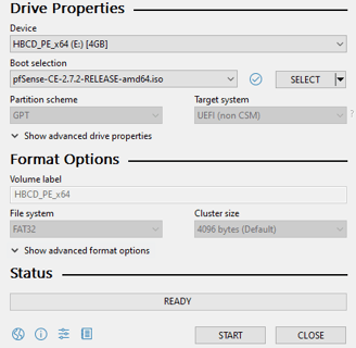
Download Rufus
Insert your USB drive: Plug your USB flash drive into your computer.
Open Rufus: Double-click the Rufus executable file to launch the application.
Select your USB drive: In the "Device" section, Rufus should automatically detect your USB drive.
Choose the ISO image: Click "Select" under "Boot selection" and browse to the location of the ISO file you want to use.
Configure settings (optional):
Partition scheme: Select "MBR" for most systems or "GPT" if you're using a newer UEFI system.
File system: Usually, Rufus will automatically set the appropriate file system based on your chosen ISO.
Volume label: Give your USB drive a name if desired.
Start the process: Click "Start" to begin creating the bootable USB drive. Once completed, disconnect the USB and plug into the new PfSense PC.
Ensure you have a network connection to the internet established before starting this process, plug an ethernet cable from the PfSense PC to your current router.
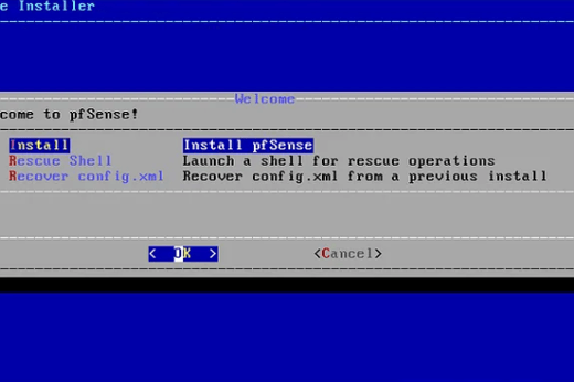
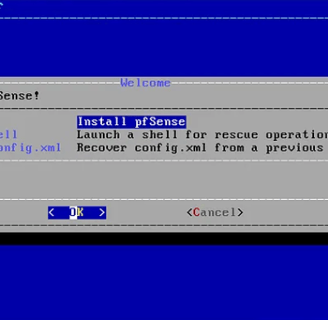
Power on the device and boot from your PfSense media. You may need to manually select the USB boot device.
Accept the license agreement, choose 'Install'
Keep default keymap, select 'Auto UEFI' (if your hardware only supports BIOS as a boot method then select that instead),
Select 'Entire Disk', click yes to confirm, select GPT click enter
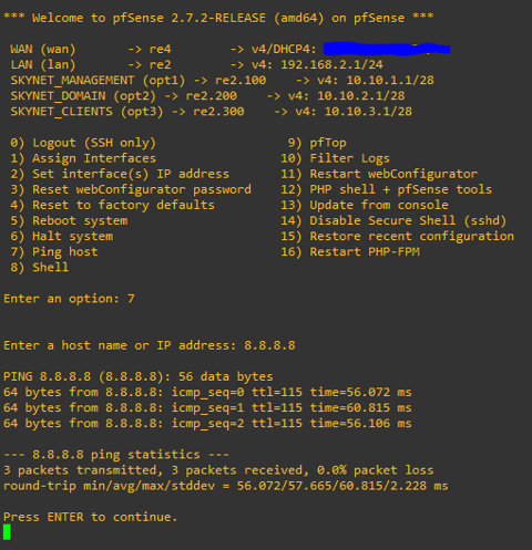
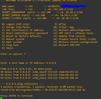
Select 'Finish' then confirm. PfSense will format the disk for you. Once finished, reboot the VM and remove the ISO from the media drive. You should see the screen below.
You should have an IP address assigned to your PfSense WAN port via your home router's DHCP service. It should be in the 192.168.x.x range.
Now let’s test to make sure we have external internet connectivity for our WAN port. Type '7' and hit enter, then try to ping Google's IP of 8.8.8.8. If you get a reply, then congratulations your PfSense is connected to the internet.
Press ENTER to continue, then select option '2', select your second network interface and assign it as your LAN interface. Use the following as your IP settings: 192.168.2.1, subnet mask 255.255.255.0, gateway 192.168.2.1
Let’s connect to the management interface on PfSense to setup the rest of our network settings using a different PC/laptop or the T7910 server. The new PfSense router and the PC/laptop/T7910 will need to be on the same network in order to interact with each other.
Launch command prompt and type "ipconfig" to ensure your PC or T7910 resolves to a 192.168.1.x address that is on the same subnet as your PfSense.
Launch Microsoft Edge and navigate to the IP address of the PfSense LAN. For example, you may navigate to https://192.168.2.1.
You can ignore any warnings as the PfSense virtual appliance has a self-signed certificate that cannot be verified by Edge. The default username for PfSense is admin and the default password is pfsense. Once logged in, there is a warning to change the default password, go ahead and do that before we continue as a security best practice.
Now let’s configure your LAN port IP address, we will need a way for wireless clients such as IoT devices to communicate.
From the PfSense Dashboard, go to 'Interfaces' and select 'Assignments', select your NIC2, click 'Add' from the right side.
Under 'General Configuration', click checkbox for Enable Interface, type 'LAN' for the Description, set the IPv4 to 'Static', leave the rest in General Configuration blank, under Static IPv4 Configuration set the IPv4 address to 192.168.2.1, this will be the gateway for this interface, change the subnet mask to /24. click 'Save' at the bottom.
Navigate to ‘Services’, then ‘DHCP Server’, enable it for the WAP interface, set IP range to 192.168.2.100-200 /24, click 'Save' at the bottom.
From the PfSense Dashboard, go to 'Interfaces' and select 'Assignments', select your NIC3, click 'Add' from the right side.
Next, we will be setting up 2 LAN ports in link aggregation, this will be to provide redundancy and will be used as the port for all of our VLANs. You also need to access PfSense by domain name eventually and we don't want to use your home router's DHCP address as it may change over time, so this link aggregation (LAGG) port IP will have a DNS name associated we will use.
Under 'General Configuration', click checkbox for Enable Interface, type ‘LAN 1’ for the Description, set the IPv4 to 'DHCP', leave the rest in General Configuration blank, click 'Save' at the bottom.
From the PfSense Dashboard, go to 'Interfaces' and select 'Assignments', select your NIC4, click 'Add' from the right side.
Under 'General Configuration', click checkbox for Enable Interface, type ‘LAN 2’ for the Description, set the IPv4 to 'DHCP', leave the rest in General Configuration blank, click 'Save' at the bottom.
Configure VLANs on your PfSense LAN interface:
From the PfSense Dashboard, go to 'Interfaces' and select 'Assignments',
Select the 'VLANs' tab and click 'Add', select 'Parent Interface' and choose 'LAN’, under 'VLAN Tag' type 100, under Description type 'Management VLAN', click 'Save'.
From the PfSense Dashboard, go to 'Interfaces' and select 'Assignments', you will see 'Available network ports' select your new VLAN and click 'Add'.
Click it to enter the 'General Configuration', change the Description to match the VLAN name. Check the box for 'Enable Interface' and change the IPv4 Configuration Type to 'Static'. Under Static IPv4 Configuration change the IP address to 10.10.1.1 with a subnet mask of /28. click 'Save', then click 'Apply'.
Do the same for the remaining network interfaces, assigning the VLAN to the same ‘LAN’ port, reference the screenshot below when adding the remaining VLANs.
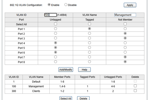
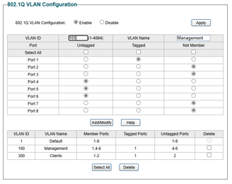
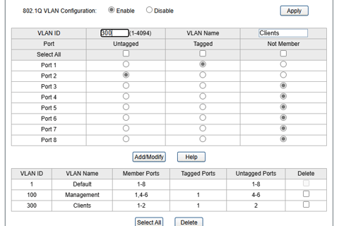
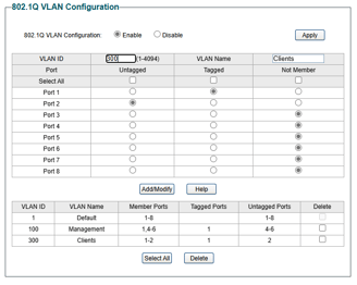
Configure VLANs on your Netgear Smart Switch:
Login to your Netgear Smart Switch, change the name of the device on the main page to “EdgeSW-TL-SG108E” so we can identify it better.
Navigate to System->IP Setting and set the static IP of 10.10.1.10, subnet mask 255.255.255.240, default gateway 10.10.1.1. Click Apply.
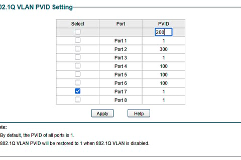
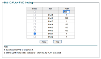
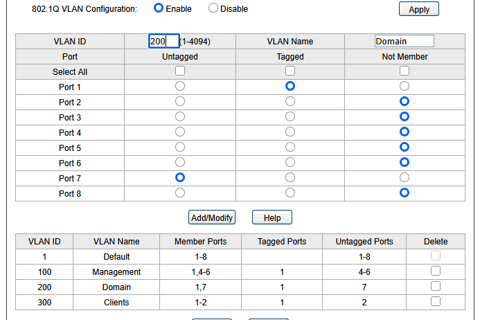
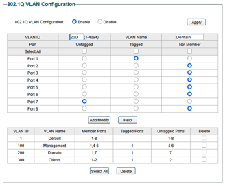
Navigate to VLAN->802.1Q VLAN and set the VLAN information based on the screenshots below, also do the same for VLAN->802.1Q PVID.
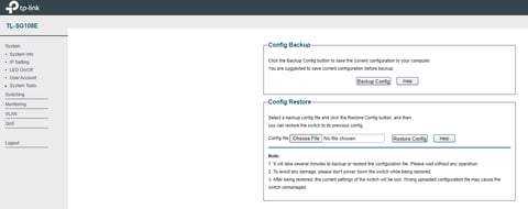
Save the configuration, navigate to System->System Tools->Backup and Restore to perform a backup of the configuration files in case you need to re-apply settings later.
At this point, we have completed the basic networking for our home lab/small office. We have separated our network into four different IP ranges: 192.168.2.x/24 for our IoT and wireless devices, 10.10.1.x/27 for our management of our physical devices in our lab, 10.10.2.x/27 for our domain services, and 10.10.3.x/24 for our domain clients. We can make optional configurations like creating LAGG interfaces on the additional ports in PfSense or further restricting VLAN communication using firewall rules. Check out these blogs for more lab projects!
OPTIONAL: Configure LAGG Interface
From the PfSense Dashboard, go to 'Interfaces' and select 'Assignments', select LAGG tab, select ports NIC3 & NIC4, select LACP (if your switch supports it) or Failover (if it doesn’t), give the interface a name, click ‘Save’.
Navigate to ‘Interfaces’ and select ‘Assignments’, click 'Add Interface' and choose the new LAGG port, click on it and go to Description assign it the name ‘LAN LAGG’, assign a static IP of 192.168.3.1/28, click ‘Save’ then click ‘Apply’.
Navigate to ‘Firewall’, then ‘Rules’, add a new rule to allow ANY IP to ANY IP, click ‘Save’.
Login to your Netgear Smart Switch, you can use the default username is admin and the default password is password.
Need documentation on configuring switch ports to use LAGG.
Plug in cables from switch to PfSense.
From the PfSense Dashboard, go to 'Interfaces' and select 'Assignments', select the 'VLANs' tab and click 'Add', select 'Parent Interface' and choose 'LAN LAGG’, under 'VLAN Tag' type 100, under Description type 'Management VLAN', click 'Save'.
From the PfSense Dashboard, go to 'Interfaces' and select 'Assignments', you will see 'Available network ports' select your new VLAN and click 'Add'. Click it to enter the 'General Configuration', change the Description to match the VLAN name. Check the box for 'Enable Interface' and change the IPv4 Configuration Type to 'Static'. Under Static IPv4 Configuration change the IP address to 10.10.1.1 with a subnet mask of /28. click 'Save', then click 'Apply'.
Do the same for the remaining network interfaces, assigning the VLAN to the same ‘LAN LAGG’ port, reference the screenshot below when adding the remaining VLANs.
OPTIONAL: Double NAT using Bridge Mode
We will be using the free and open-source router/firewall called 'PfSense' and will be installing it on virtual machine. Pfsense offers a Community Edition that we will use, it also offers features such as load balancing, unified threat management, and more. This will run alongside your home router/firewall and only be used to administer VMs and wired clients in your lab domain. This way we can make changes and revert changes to router settings without affecting the other users on your home network or office (such as your wife and kids when they are watching Netflix).
Login to your server, navigate to Control panel->All Control Panel Items-Network and Sharing Center and click the 'change adapter settings' on the left.
If you have a wireless network card in your server, you can enable it and leave it as DHCP so you can get an IP address. If you do not have a wifi NIC, then let's go ahead and setup your 8-port Netgear switch first.
Power on your switch and plug in an Ethernet cable from port 8 on the switch to an open port on your router (you likely will need a long cable for this). Attach another Ethernet cable from port 1 on the switch to the first port on your 4-port NIC on your server so you can get and IP established. You should see the connection status change on the NIC that you connected to your switch, rename that NIC "NIC 1 (WAN)".
Navigate to Hyper-V Manager, click 'Actions' in the right pane and select 'Virtual Switch Manager', in the left pane click 'New Virtual Network Switch' name it 'WAN', under Connection type select 'External network' and select NIC 1 on your 4-port network adapter, select the checkbox for 'Allow management operating system to share the network adapter', click Apply. Rename
Repeat for the remaining 3 NICs on your 4-port network adapter, naming them as follows: NIC 2 (LAN), NIC 3 (SkyNet), NIC 4 you can leave it for now.
Navigate back to Control panel->All Control Panel Items-Network and Sharing Center and click the 'change adapter settings' on the left. You should see 4 new virtual adapters corresponding to the physical NICs. Rename the virtual NIC ports as follows: NIC 1 "vmnic0 (WAN)", NIC 2 "vmnic1 (LAN)", NIC 3 "vmnic2 (Skynet)", NIC 4 "vmnic3".
Right click the first virtual NIC you made (not the physical one) and select properties, click properties again, select "set static IP address" and set the IP to 10.10.1.14, subnet mask 255.255.255.240, default gateway 10.10.1.1, DNS can be blank.
Right click the second virtual NIC you made (not the physical one) and select properties, click properties again, select "set static IP address" and set the IP to 10.10.2.14, subnet mask 255.255.255.240, default gateway 10.10.2.1, DNS can be blank.
Right click the third virtual NIC you made (not the physical one) and select properties, click properties again, select "set static IP address" and set the IP to 10.10.3.14, subnet mask 255.255.255.240, default gateway 10.10.3.1, DNS can be blank.
The fourth NIC can be left alone for now. Plug in an Ethernet cable from your NIC1
We will now create our virtual router using Pfsense. Download the latest PfSense image so we can get started creating the virtual machine for it.
Launch 'Hyper-V Manager' from your T7910 server, right-click your server from the upper left, select 'New' then 'New Virtual Machine'.
Click 'Next', name your VM and select the destination to store the VM (on our easy setup it is the drive name of our software-based RAID), click 'Next'.
Specify 'Generation 2' as most VMs we create will use Generation 2 which supports UEFI and has builtin support for UEFI operating systems, click 'Next'.
The minimum required RAM for PfSense is 1GB but we will give it 4GB (4096MB), leave Dynamic Memory unchecked, click 'Next'.
We will be adding additional vNICs to this VM but for now select your WAN virtual switch we made earlier, click 'Next'.
Name your VHDX the same name as your VM and ensure it is stored in the same location as your VM config files from earlier, adjust the size to 40GB, click 'Next'.
Select 'Install an Operating System from a bootable CD/DVD-ROM, then choose the PfSense ISO you downloaded, click 'Next'.
Check that everything looks correct then click 'Finish'.
Right-click the VM and select 'Edit Settings', select 'Add Hardware' and select 'Network Adapter' do not select the 'Legacy Network Adapter' option, in the virtual switch dropdown select your 'LAN' switch, select 'Add Hardware' and select 'Network Adapter', in the virtual switch dropdown select your 'SKYNET' switch (or whatever you named yours), click 'Apply' then 'Ok'.
Go to the Processor tab and increase the number to '2', click 'Ok'.
Right-click the VM, select 'Connect', then click 'Start' to power on the VM, select 'Ok' to install PfSense.
--See instructions above to install and configure PfSense
Under 'General Configuration', click checkbox for Enable Interface, type 'Storage Services' for the Description, set the IPv4 to 'Static', leave the rest in General Configuration blank, under Static IPv4 Configuration set the IPv4 address to 10.10.4.1, this will be the gateway for this interface, change the subnet mask to /24. Click 'Save' at the bottom.
From the PfSense Dashboard, go to 'Interfaces' and select 'Assignments', select the 'VLANs' tab and click 'Add', select 'Parent Interface' and choose 'LAN - Management Services', under 'VLAN Tage' type 100, under Description type 'Management VLAN', click 'Save'.
From the PfSense Dashboard, go to 'Interfaces' and select 'Assignments', you will see 'Available network ports' select your new VLAN and click 'Add'. Click it to enter the 'General Configuration', change the Description to match the VLAN name. Check the box for 'Enable Interface' and change the IPv4 Configuration Type to 'Static'. Under 'Static IPv4 Configuration change the IP address to 10.10.x.x with a subnet mask of /28. click 'Save', then click 'Apply'. Do the same for the remaining network interfaces.
NEXT: Administer Your Home Lab